Input/Output devices
Input/Output devices are the devices that are responsible for the input/output operations in a computer system.
Basically there are following two types of input/output devices:
- Block devices
- Character devices
Block Devices
A block device stores information in block with fixed-size and own-address.
It is possible to read/write each and every block independently in case of block device.
In case of disk, it is always possible to seek another cylinder and then wait for required block to rotate under head without mattering where the arm currently is. Therefore, disk is a block addressable device.
Character Devices
A character device accepts/delivers a stream of characters without regarding to any block structure.
Character device isn't addressable.
Character device doesn't have any seek operation.
There are too many character devices present in a computer system such as printer, mice, rats, network interfaces etc. These four are the common character devices.
Input/Output Devices Examples
Here are the list of some most popular and common input/output devices:
- Keyboard
- Mouse
- Monitor
- Modem
- Scanner
- Laser Printer
- Ethernet
- Disk
Kernel I/O Subsystem
The kernel provides many services related to I/O. Several services such as scheduling, caching, spooling, device reservation, and error handling – are provided by the kernel, s I/O subsystem built on the hardware and device-driver infrastructure. The I/O subsystem is also responsible for protecting itself from errant processes and malicious users.
- I/O Scheduling –To schedule a set of I/O requests means to determine a good order in which to execute them. The order in which the application issues the system call is the best choice. Scheduling can improve the overall performance of the system, can share device access permission fairly to all the processes, reduce the average waiting time, response time, turnaround time for I/O to complete.OS developers implement schedules by maintaining a wait queue of the request for each device. When an application issue a blocking I/O system call, The request is placed in the queue for that device. The I/O scheduler rearranges the order to improve the efficiency of the system.
- Buffering –A buffer is a memory area that stores data being transferred between two devices or between a device and an application. Buffering is done for three reasons.
- The first is to cope with a speed mismatch between producer and consumer of a data stream.
- The second use of buffering is to provide adaptation for data that have different data-transfer sizes.
- The third use of buffering is to support copy semantics for the application I/O, “copy semantic ” means, suppose that an application wants to write data on a disk that is stored in its buffer. it calls the write() system’s call, providing a pointer to the buffer and the integer specifying the number of bytes to write.
- Caching –A cache is a region of fast memory that holds a copy of data. Access to the cached copy is much easier than the original file. For instance, the instruction of the currently running process is stored on the disk, cached in physical memory, and copied again in the CPU’s secondary and primary cache.
The main difference between a buffer and a cache is that a buffer may hold only the existing copy of a data item, while a cache, by definition, holds a copy on faster storage of an item that resides elsewhere.
- Spooling and Device Reservation –A spool is a buffer that holds the output of a device, such as a printer that cannot accept interleaved data streams. Although a printer can serve only one job at a time, several applications may wish to print their output concurrently, without having their output mixes together.
The OS solves this problem by preventing all output from continuing to the printer. The output of all applications is spooled in a separate disk file. When an application finishes printing then the spooling system queues the corresponding spool file for output to the printer.
- Error Handling –An Os that uses protected memory can guard against many kinds of hardware and application errors so that a complete system failure is not the usual result of each minor mechanical glitch, Devices, and I/O transfers can fail in many ways, either for transient reasons, as when a network becomes overloaded or for permanent reasons, as when a disk controller becomes defective.
- I/O Protection –Errors and the issue of protection are closely related. A user process may attempt to issue illegal I/O instructions to disrupt the normal function of a system. We can use the various mechanisms to ensure that such disruption cannot take place in the system.To prevent illegal I/O access, we define all I/O instructions to be privileged instructions. The user cannot issue I/O instruction directly.
I/O buffering
A buffer is a memory area that stores data being transferred between two devices or between a device and an application.
Uses of I/O Buffering :
- Buffering is done to deal effectively with a speed mismatch between the producer and consumer of the data stream.
- A buffer is produced in main memory to heap up the bytes received from modem.
- After receiving the data in the buffer, the data get transferred to disk from buffer in a single operation.
- This process of data transfer is not instantaneous, therefore the modem needs another buffer in order to store additional incoming data.
- When the first buffer got filled, then it is requested to transfer the data to disk.
- The modem then starts filling the additional incoming data in the second buffer while the data in the first buffer getting transferred to disk.
- When both the buffers completed their tasks, then the modem switches back to the first buffer while the data from the second buffer get transferred to the disk.
- The use of two buffers disintegrates the producer and the consumer of the data, thus minimizes the time requirements between them.
- Buffering also provides variations for devices that have different data transfer sizes.
Types of various I/O buffering techniques :
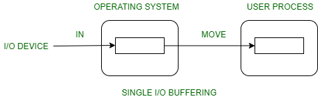
Block oriented device –
- System buffer takes the input.
- After taking the input, the block gets transferred to the user space by the process and then the process requests for another block.
- Two blocks works simultaneously, when one block of data is processed by the user process, the next block is being read in.
- OS can swap the processes.
- OS can record the data of system buffer to user processes.
Stream oriented device –
- Line- at a time operation is used for scroll made terminals. User inputs one line at a time, with a carriage return signaling at the end of a line.
- Byte-at a time operation is used on forms mode, terminals when each keystroke is significant.
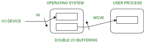
2. Double buffer :
Block oriented –
- There are two buffers in the system.
- One buffer is used by the driver or controller to store data while waiting for it to be taken by higher level of the hierarchy.
- Other buffer is used to store data from the lower level module.
- Double buffering is also known as buffer swapping.
- A major disadvantage of double buffering is that the complexity of the process get increased.
- If the process performs rapid bursts of I/O, then using double buffering may be deficient.
Stream oriented –
- Line- at a time I/O, the user process need not be suspended for input or output, unless process runs ahead of the double buffer.
- Byte- at a time operations, double buffer offers no advantage over a single buffer of twice the length.
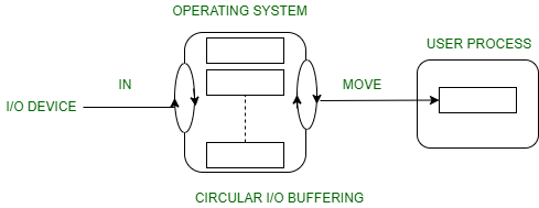
3. Circular buffer :
- When more than two buffers are used, the collection of buffers is itself referred to as a circular buffer.
- In this, the data do not directly passed from the producer to the consumer because the data would change due to overwriting of buffers before they had been consumed.
- The producer can only fill up to buffer i-1 while data in buffer i is waiting to be consumed.
Disk Storage
Hard Disk Structure In OS
Hard disk is secondary storage which stores the large amount of data. The Hard disk drive contains a dozens of disks. These disks are also known as platters. These platters are mount over the spindle which rotates in any direction i.e. clockwise or anti-clockwise. Lets look at hard disk structure in OS.
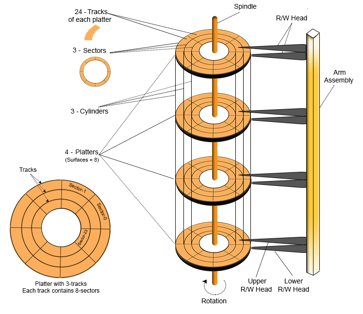
Platter
- The Platter is made of aluminum or iron oxide.
- Platter diameter range is 1.8 inches to 5.25 inches
- Each platter contains 2 surfaces and 2 Read/Write Head. One Read/Write head requires for one surface of the platter. So, other R/W head use for other surface to store the information’s.
- Every platter holds the same no. of tracks.
- Multiple platters increase the storage capacity.
R/W Head
- R/W Heads moves forth and back over the platter surfaces to Read or Write the data on sectors.
- Read/Write heads does not touch to platters surface. The data written over the platter surface is done through magnetic field. If R/W Head touches over the surface of platter then bad sectors may creates. Had disk may damage due to these bad sectors.
Tracks
- Circular areas of disk are known as tracks.
- There may be more than a 1000 tracks on a 3.5 inch hard disk and sector size. Track Numbering start with zero at outermost track.
Sectors
Tracks are further divided into number of small units; these small units are known as sectors. Sectors are the smallest physical storage units on disk. Size of each sector is almost always 512 Bytes. Sector Numbering start with 1 at outermost tracks.
Cylinder
All Corresponding tracks with same radius of all platters in the Hard disk are known as cylinders. In simple words we say
“Each tack of all platters with same radius is called a cylinder”So, Number of tracks in platter is always equal to number of cylinders. For example, a hard disk, where each platter contains 600 tracks then the number of cylinders will also be 600 in the hard disk.
Cylinder Numbering start with zero at outermost cylinder.
Cluster
Cluster is also known as blocks. Group of sectors makes a cluster. There may be 64 or sectors in a cluster. These clusters are used by OS to Read/Write the data.
Disk Capacity
As we know there are number of platters in the hard disk. Each platter contains two R/W heads. There are number of cylinder/tracks in the hard disk. Each track is divided into number of sectors. And each sector has some size but mostly size of sector is 512 Bytes.
Structure of a magnetic disk
A magnetic disk contains several platters. Each platter is divided into circular shaped tracks. The length of the tracks near the centre is less than the length of the tracks farther from the centre. Each track is further divided into sectors, as shown in the figure.
Tracks of the same distance from centre form a cylinder. A read-write head is used to read data from a sector of the magnetic disk.
The disk is divided into tracks. Each track is further divided into sectors. The point to be noted here is that outer tracks are bigger in size than the inner tracks but they contain the same number of sectors and have equal storage capacity. This is because the storage density is high in sectors of the inner tracks where as the bits are sparsely arranged in sectors of the outer tracks. Some space of every sector is used for formatting. So, the actual capacity of a sector is less than the given capacity.
Read-Write(R-W) head moves over the rotating hard disk. It is this Read-Write head that performs all the read and write operations on the disk and hence, position of the R-W head is a major concern. To perform a read or write operation on a memory location, we need to place the R-W head over that position. Some important terms must be noted here:
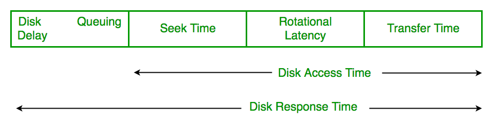
- Seek time – The time taken by the R-W head to reach the desired track from it’s current position.
- Rotational latency – Time taken by the sector to come under the R-W head.
- Data transfer time – Time taken to transfer the required amount of data. It depends upon the rotational speed.
- Controller time – The processing time taken by the controller.
- Average Access time – seek time + Average Rotational latency + data transfer time + controller time.
Note:Average Rotational latency is mostly 1/2*(Rotetional latency).
In questions, if the seek time and controller time is not mentioned, take them to be zero.
If the amount of data to be transferred is not given, assume that no data is being transferred. Otherwise, calculate the time taken to transfer the given amount of data.
The average of rotational latency is taken when the current position of R-W head is not given. Because, the R-W may be already present at the desired position or it might take a whole rotation to get the desired sector under the R-W head. But, if the current position of the R-W head is given then the rotational latency must be calculated.
Question 01: Let suppose there are 8 platters in hard disk drive. As each platters has two surfaces so 16 surfaces will be there in hard drive. Therefore, required R/W head will also be 16. Suppose, there are 1,024 cylinders and 128 sectors in each track. The sector size is 512 bytes.Then
A). Calculate Disk Size?
B). How many number of bits required to represent the disk size?
Part A. Solution
Size of Hard Disk = Cylinder x Heads X Sectors x Sector-Size
= 1,024 x 16 x 128 x 512 Bytes
=  210 + 24 + 27 + 29 Bytes = 230Bytes = 2GB
Part B. Solution
As 2GB = 230 So, 30 bits are required to represent 2GB hard disk.Question-02: Find the size of Single platter if track size 1KB and there are 1024 cylinder?
Solution: As there is a single platter So, Heads requirement will be 2.
Size of Platter = Cylinder x Heads X track size (because, Track size = Sectors x Sector-Size)
= 210 + 21 + 210 Bytes
=21+220 Bytes = 2MB
Question 03: Why does sector number addressing in CHS (Cylinder Head Sector) start at sector 1 and not 0?
Answer: For all translation modes, Cylinder (C) =0, Head (H) =0 and Sector (S) =1 is equivalent to Logical Block Address (LBA) =0. So the value of Sector is always 1.
- What is the capacity of the hard disk?Disk capacity = surfaces * tracks/surface * sectors/track * bytes/sectorDisk capacity = 4 * 64 * 128 * 256Disk capacity = 8 MB
- The disk is rotating at 3600 RPM, what is the data transfer rate?60 sec -> 3600 rotations1 sec -> 60 rotationsData transfer rate = number of rotations per second * track capacity * number of surfaces (since 1 R-W head is used for each surface)Data transfer rate = 60 * 128 * 256 * 4Data transfer rate = 7.5 MB/sec
- The disk is rotating at 3600 RPM, what is the average access time?Since, seek time, controller time and the amount of data to be transferred is not given, we consider all the three terms as 0.Therefore, Average Access time = Average rotational delayRotational latency => 60 sec -> 3600 rotations1 sec -> 60 rotationsRotational latency = (1/60) sec = 16.67 msec.Average Rotational latency = (16.67)/2= 8.33 msec.Average Access time = 8.33 msec.
Logical structure
Logical division of hard disk is generally divided into 5 basic terms which are
- MBR (Master Boot Record)
- DBR (DOS Boot Record)
- FAT (File Allocation Tables)
- Root Directory
- Data Area