Bare Machine and Resident Monitor
The Bare Machine and Resident Monitor are not directly related to the operating system but while we study about memory management these components are really important to study, so let’s study them one by one and then their working.
Bare Machine:
So basically, Bare machine is logical hardware which is used to execute the program in the processor without using the operating system. as of now, we have studied that we can’t execute any process without the Operating system. But yes, with the help of the Bare machine we can do that.
Initially, when the operating systems are not developed, the execution of an instruction is done by directly on hardware without using any interfering hardware, at that time the only drawback was that the Bare machines accepting the instruction in only machine language, due to this those person who has sufficient knowledge about Computer field are able to operate a computer. so, after the development of the operating system Bare machine is referred to as inefficient.
Resident Monitor:
In this section, if we talk about how the code runs on Bare machines, then this component is used, so basically, the Resident Monitor is a code that runs on Bare Machines.
The resident monitor works like an operating system that controls the instructions and performs all necessary functions. It also works like job sequencer because it also sequences the job and sends them to the processor.
After scheduling the job Resident monitors loads the programs one by one into the main memory according to their sequences. One most important factor about the resident monitor is that when the program execution occurred there is no gap between the program execution and the processing is going to be faster.
The Resident monitors are divided into 4 parts as:
1. Control Language Interpreter
2. Loader
3. Device Driver
4. Interrupt Processing
These are explained as following below.
1. Control Language Interpreter:
The first part of the Resident monitor is control language interpreter which is used to read and carry out the instruction from one level to the next level.
2. Loader:
The second part of the Resident monitor which is the main part of the Resident Monitor is Loader which Loads all the necessary system and application programs into the main memory.
3. Device Driver:
The third part of the Resident monitor is Device Driver which is used to managing the connecting input-output devices to the system. So basically, it is the interface between the user and the system. it works as an interface between the request and response. request which user made; Device driver responds that the system produces to fulfill these requests.
4. Interrupt Processing:
The fourth part as the name suggests, it processes the all occurred interrupt to the system.

Fixed (or static) Partitioning in Operating System
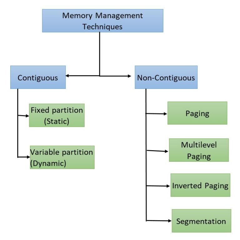
Fixed Partitioning
Fixed partitioning is also known as Static partitioning. It is an earliest (1960) technique, in which main memory is divided into equal or different sizes of partitions. OS resides in first partition and other processes reside in other partitions of main memory.
It is a very simplest form of contiguous memory allocation and very easy to implement. Fixed partitions is of two types,
1. Equal size partitions
2. Unequal Size Partitions
Consider a main memory size of 30MB.

1. Equal sized Fixed Partition
Consider a First Fit Algorithm for Memory Allocation in equal sized fixed partition. Let suppose, Main memory has five partitions with each size 6MB and five incoming processes (P1 to P5) with sizes 2MB, 6MB, 3MB, 4MB, 6MB respectively.

- Internal fragmentation
Internal fragmentation for Partition 1 = size of partition - size of process = 6 - 2 = 4MBInternal fragmentation for Partition 2 = size of partition - size of process = 6 - 6 = 0MBInternal fragmentation for Partition 3 = size of partition - size of process = 6 - 3 = 3MBInternal fragmentation for Partition 4 = size of partition - size of process = 6 - 4 = 2MBInternal fragmentation for Partition 5 = size of partition - size of process = 6 - 6 = 0MB
- External fragmentation
External fragmentation = Total sum of internal fragmentation = 4+0+3+2+0 = 9MB
2. Unequal Fixed Partition
Consider a First Fit Algorithm for Memory Allocation in Unequal sized fixed partition. Let suppose, Main memory has five partitions with sizes 10MB, 6MB, 4MB, 4MB, 6MB respectively and five incoming processes (P1 to P5) with sizes 2MB,6MB,3MB,4MB,6MB respectively.
- Internal fragmentation
Internal fragmentation for Partition 1 = size of partition - size of process = 10 - 2 = 8MBInternal fragmentation for Partition 2 = size of partition - size of process = 6 - 6 = 0MBInternal fragmentation for Partition 3 = size of partition - size of process = 4 - 3 = 1MBInternal fragmentation for Partition 4 = size of partition - size of process = 4 - 4 = 0MBInternal fragmentation for Partition 5 = size of partition - size of process = 6 - 6 = 0MB
- External fragmentation
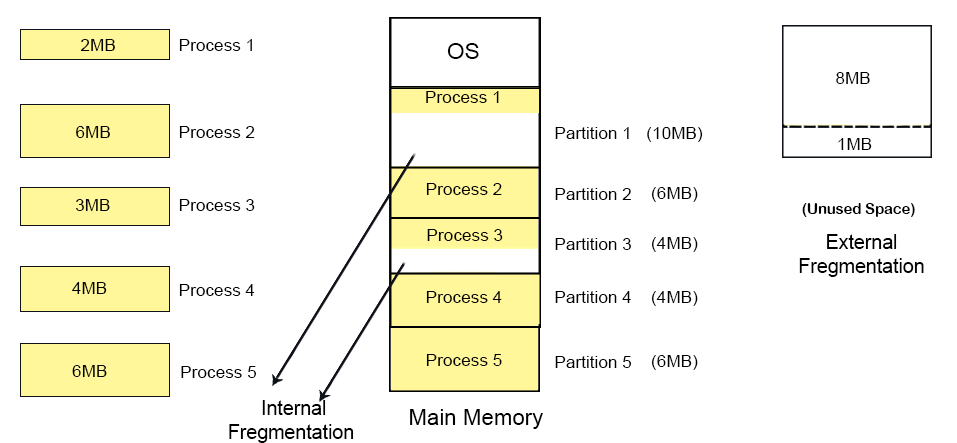
Conditions for fixed Partitions:
1. One process cannot reside in more than one partition.
Explain: if there are two empty partitions of 10 KB and 10KB in RAM and incoming process size is 20 KB then Main memory can’t accommodate it.
2. Only one process in one partition because more than one process cannot load in one partition.
Explain: At the time when P7 arrive, each partition contains one process. So, P7 cannot load even 3MB space is available in the form of internal fragmentation.

Conclusion: Each partition in RAM can accommodate only one process. That’s why, if there are 50 partitions in RAM then only 50 processes can come in RAM.
Note: if the process size is greater than partition size then that process cannot load into main memory.
Drawbacks of Fixed Partitions:
1. Internal Fragmentation
If process size is less than the total size of partition then extra size of partition is wasted. This wastage of memory is internal fragmentation.
As shown in the image above, the 4 MB in partition 2 is unused, the 3 MB in partition 3 is unused, 6 MB in partition 4 is unused and 5 MB in partition 5 is unused. Then This 4MB, 3MB, 6MB and 5MB in partition 2, 3, 4, and 5 respectively is internal fragmentation.
2. External Fragmentation
The total unused space of various partitions is external fragmentation. It cannot load the processes even though there is space available due to internal fragmentation.
As shown in the image above, the 4 MB in partition 2 is unused, the 3 MB in partition 3 is unused, 6 MB in partition 4 is unused and 5 MB in partition 5 is unused. Therefore, the total 18MB unused space from different partitions is the external fragmentation.
3. Limitation on the size of the process
If the process size is greater than the size of maximum sized partition then that process could not be loaded into the memory.
4. Degree of multi-programming is less
In fixed partitioning, the degree of multi-programming is fixed and very less. So, Degree of multi programming does not increase even the processes is too small.
Variable (or dynamic) Partitioning
Dynamic Partitioning
Dynamic partitioning is also known as variable partitioning. It eliminates the factor of internal fragmentation. In this technique, the size of the partition is declared at the loading time of the process. It does not have a predefined memory partition.
OS itself loads in the first partition. The remaining space is divided into different parts. These parts are known as partitions. Every partition size will be equal to the size of the that incoming process. So, partitions sizes are not similar.
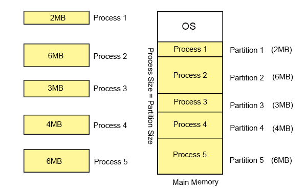
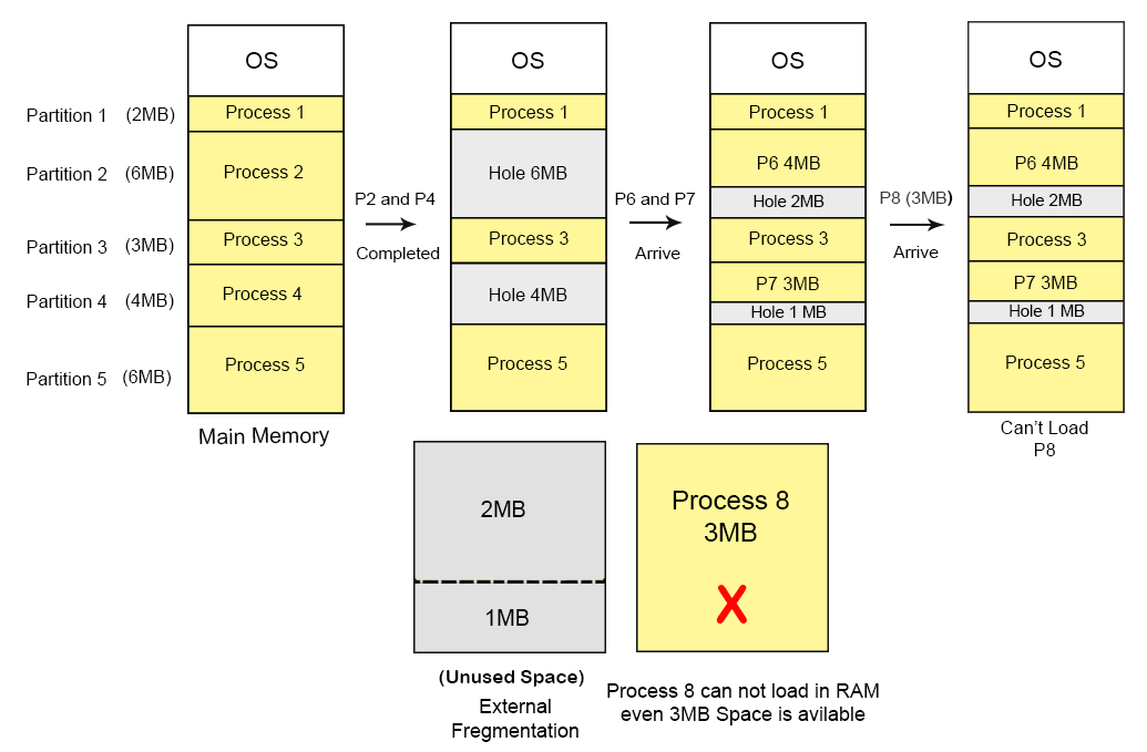
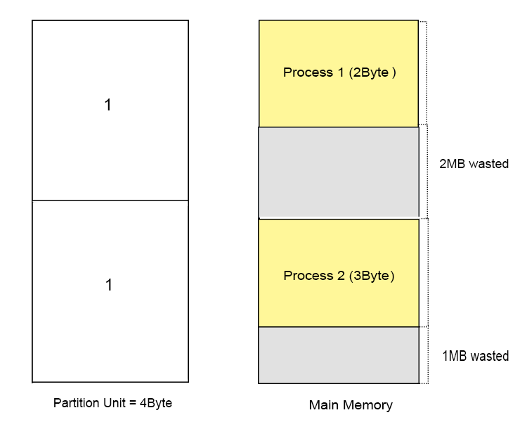
There will be never internal fragmentation in dynamic partition but external fragmentation may exist as explained in below diagram.
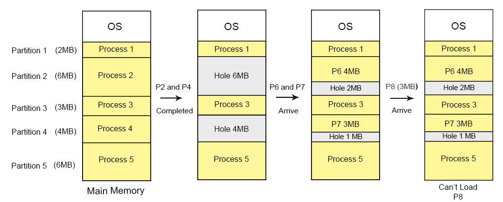
2MB unused space in Partition 2 and 1MB unused space in partition 4 leads toward external fragmentation because P8 with size 3MB can’t load. Therefore, we can say this unused space is external fragmentation.
It is not an internal fragmentation because the size of 2MB can be accommodated in partition 2.
Conditions for Dynamic Partitions
We know, the partitions are allocated to process at run time and there is no problem with partition size but the condition is
1. One process cannot reside in more than one partition. (spanning not allowed)
Explain: As there are two empty partitions of 1MB and 4MB in RAM and incoming process size is 5MB then Main memory can’t accommodate it.
Advantages of Dynamic Partitioning over fixed partitioning
1. No Internal Fragmentation
As process size is always equal to partition size then there will be no internal fragmentation.
2. No Limitation of process size
As partition size declare at loading time. So, there is no limitation of process size.
3. Degree of multi-programming is dynamic
Due to the absence of internal fragmentation, more processes can be loaded into the memory at a time
Disadvantages of dynamic partitioning
1. External Fragmentation
If there is no internal fragmentation then it doesn’t mean that there will not be external fragmentation.
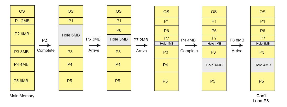
Let’s consider there are four processes P1 (2 MB), P2 (6 MB), P3 (3 MB), P4 (4 MB) and P5 (6 MB). These are loaded in the respective partitions 1, 2, 3, 4 and 5 of the main memory.
After some time Process 2 and P4 are completed and their assigned space is free. Now there are two free-space partitions (6 MB and 4 MB) are available in the main memory. After loading of process P6 and P7 in partition 2 and 4 respectively. There is still free space of 2MB and 1MB in partition 2 and 4 respectively. But this free-space cannot load the process 8 of 3 MB into the memory. It is Because of, the free-space exists at different location of main memory.
That’s why, this 3MB free-space leads toward external fragmentation. As showing in the following diagram,
Difference between Fixed Partitioning and Variable Partitioning:
S.NO. | Fixed partitioning | Variable partitioning |
1. | In multi-programming with fixed partitioning the main memory is divided into fixed sized partitions. | In multi-programming with variable partitioning the main memory is not divided into fixed sized partitions. |
2. | Only one process can be placed in a partition. | In variable partitioning, the process is allocated a chunk of free memory. |
3. | It does not utilize the main memory effectively. | It utilizes the main memory effectively. |
4. | There is presence of internal fragmentation and external fragmentation. | There is external fragmentation. |
5. | Degree of multi-programming is less. | Degree of multi-programming is higher. |
6. | It is more easier to implement. | It is less easier to implement. |
7. | There is limitation on size of process. | There is no limitation on size of process. |
Allocation in Memory (First-Fit)
Allocation Methods In Contiguous
In continuous memory management there are 4 algorithms. Through these algorithms we can allocate the upcoming process in proper hole to avoid from internal fragmentation. These algorithms are known as Partition Allocation Methods In Contiguous.
1. First Fit: In this algorithm OS allocate the process to first Hole that is big enough.
It is very fast and easy to implement
First fit algorithm starts scanning the partitions from the beginning of memory every time to load new process in main memory. When it found first big enough partition, that can accommodate the loading process, then scanning stop and process loaded successfully. Explanation given under
2. Next Fit: Next fit is modified of first fit but it will search for the first big enough partition from the last allocation partition.
3. Best Fit: In this algorithm OS allocate the process to that partition which is first smallest enough (among the all free available partition) to accommodate that process.
It is time consuming algorithm but internal fragmentation factor is minimized.
4. Worst Fit: In this algorithm OS allocate the process to that partition which is first Largest enough (among the all free available partition) to accommodate that process.
Allocation Methods in FIXED and Dynamic Partitions explained under,
1. Fix Sized Partitions
Explain with example
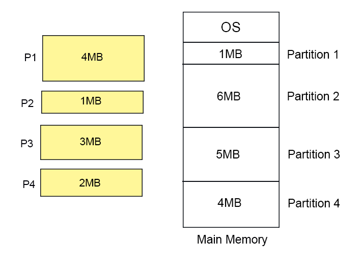
Let suppose we have four FIX sized partitions with size 1MB, 6MB, 5MB, and 4MB respectively and four incoming processes (P1 to P4) with sizes 4MB, 1MB, 3MB and 2MB respectively.
 Let’s start the First Fit algorithm execution from above mentioned processes and memory.
Let’s start the Next Fit algorithm execution from above mentioned processes and memory. 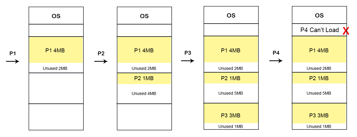
Let’s start the Best Fit algorithm execution from above mentioned processes and memory.

Let’s start the Worst Fit algorithm execution from above mentioned processes and memory.
2. Dynamic Partitions
Explain With Example
Let suppose we have four empty Dynamic sized partitions with size 1MB, 6MB, 5MB, and 4MB respectively
and four incoming processes (P1 to P4) with sizes 4MB, 1MB, 3MB and 2MB respectively.
Case 01: First Fit

Case 02: Next Fit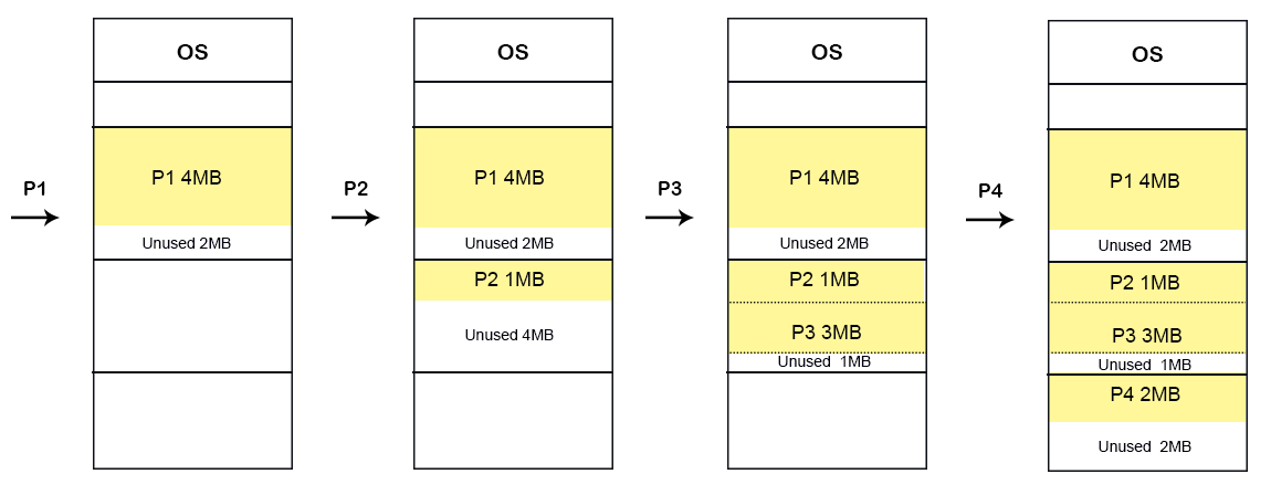
Case 03: Best Fit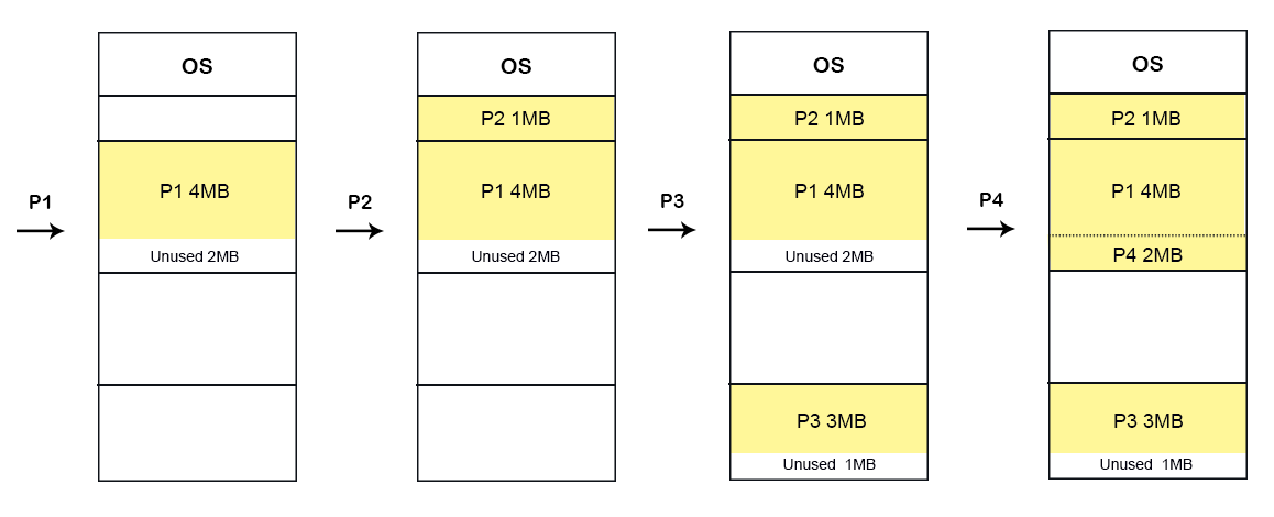
Case 04: Worst Fit
Practice Questions
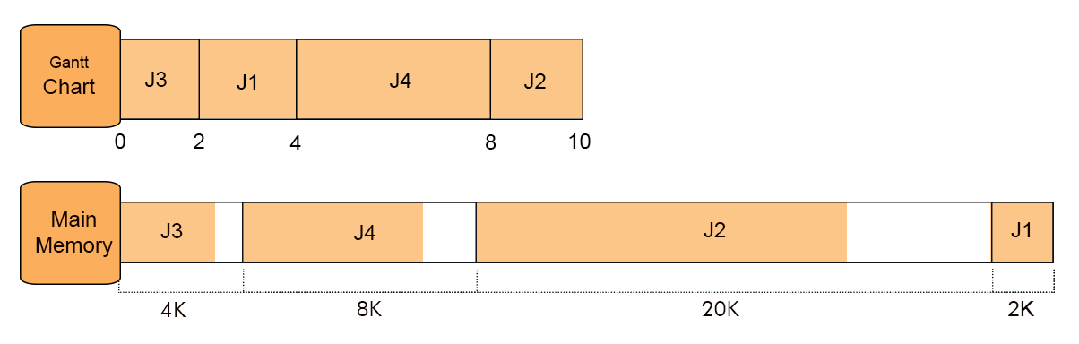
Question 1: if there are 8 jobs (J1 to J8) arrive at time zero having job sizes 2K, 14K, 3K, 6K, 6K, 10K, 7K, 20K respectively and there usage time 4, 10, 2, 8, 4, 1, 8, 6 respectively then calculate the time at which Job 7 will completed by applying BEST FIT algorithm.
Solution
Step 1

As it is best fit case, so J1 fit in 2K, J2 in 20K, J3 in 4K and J4 in 8K memory Partitions. Timeline of completion time of all jobs given below
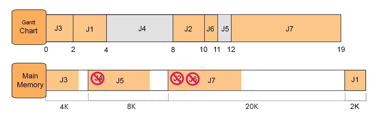
Step 2
J5 came now, but the memory is already full. J5 wait for termination of any Job so J5 will check the timeline to find his Place in memory. At Point 2 Job J3 terminate but its space is not enough to accommodate J6 size and the same case with J1 at point 4.

So at point 8 Job J4 is completed and J5 enter at point 8 and completed at point 12.
Step 3
J6 came now, but the memory is already full. J6 wait for termination of any Job so J6 will check the timeline to find his Place in memory. At Point 2 Job J3 terminate but its space is not enough to accommodate J6 size and the same case with J1 at point 4.

So at point 10 Job J2 is completed and J6 enter at point 8 and completed at point 11.
Because its execution time is 1.
Step 4
J7 came now, follow the previous rules, so it will replace J6 and terminate at point 19.
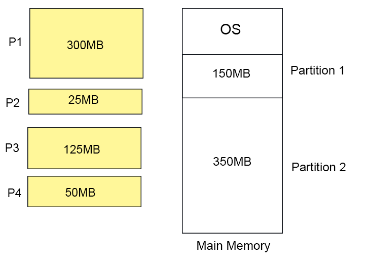
Question2: In dynamic partitions, If the processes requests are in given order
- 300MB
- 25MB
- 125MB
- 50MB
and two memory blocks are available of size 150MB and 350MB.
Which of the following partition allocation method is fulfill the above conditions?
A) Best fit but not first fit.
B) Both first fit & best fit.
C) First fit but not best fit.
D) Neither first fit nor best fit.
Solution
According to First Fit

According to Best Fit

So option C is the correct choice.
Compaction
As we know, fixed and dynamic partitioning suffers from external fragmentation. However, this issue can overcome through Compaction.
In compaction, all the holes are made contiguous and all the loaded processes in different partitions are brought together by OS.
Now merged holes can accommodate new processes according to their needs. This method is also known as de-fragmentation. Let us explain through diagram

After compaction the process P8 can be loaded into main memory easily because contiguous space is available now.
Problems with Compaction
Efficiency of the system also decrease because CPU set idle at the time of compaction.
Explanation: At the time of compaction, CPU stops execution of current process because it will resume the process from somewhere else after compaction. If CPU does not stop the execution of a process then it may execute the instructions from somewhere else locations instead of next instruction of same process in memory.
Note: Consider an OS require 6 NS time to transfer 1-B then, 1 MB transfer needs (1 X 2^20) X (6 X 10 ^ -9) seconds.
So, large the amount of data to transfer, require a huge amount of time.
1. Complex Memory Allocation
In Fixed partitioning, the list of partitions is made once and will never change.
As allocation and de-allocation takes place very frequently in dynamic memory allocation. So, partition size also change each time in allocation and de-allocation. That’s why, it is very difficult for OS to manage everything at a time.
How to manage allocation and de-allocation?
OS use the following data structures for memory allocation and de-allocation.
- Bit Map
- Linked List
Both of these concepts, we will discuss in the next post.
Bit Map in Dynamic Partitioning
Bit Map in Dynamic Partitioning
Bit Map is a data structure to store the details about allocation and reallocation of process. For this purpose the main memory is divided into the number of allocation units. One or more allocation units may assign to single process according to the need of that process. Size of each allocation unit is same which is fix by OS, that never changed. Although, the partition size from process to process may vary due to dynamic partitioning.
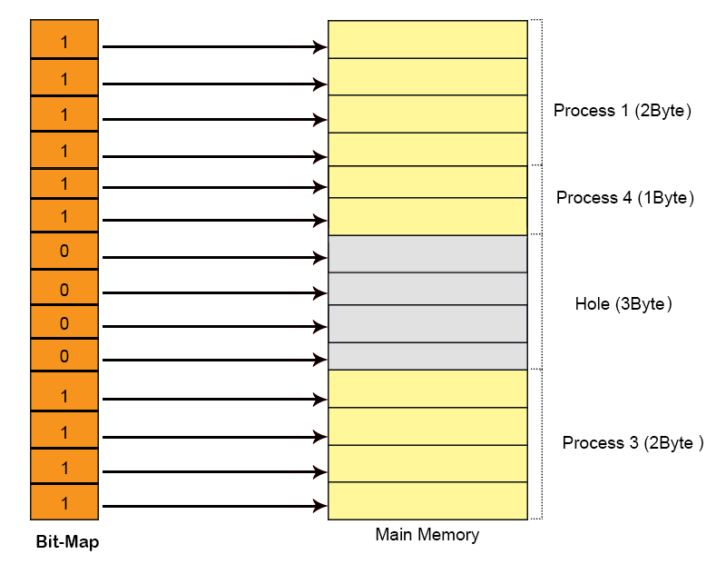
The main task of OS is to check whether the partitions are filled or free. For this purpose, flag bits are used. either process or hole in Allocation memory is represented by a flag bit of bitmap. 0 represents Hole and 1 represents the Process in bit map.
Let’s explain Bit Map in Dynamic Partitioning with Example
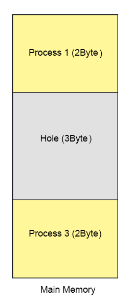
Suppose we have a main memory of 7 Byte. Where 2Byte is allocated to process 1, 3Bytes are allocated to Process 2 and 2 byte allocated to Process 3. After some time Process 2 complete its execution which create a hole of 3 byte in main memory shown in below diagram.
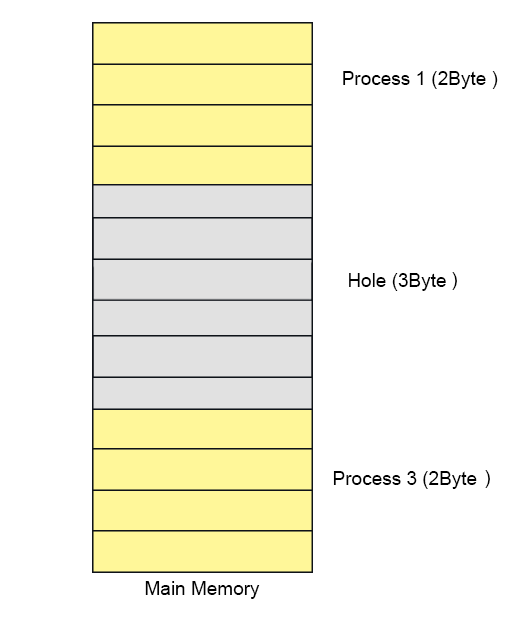
Let’s divide the main memory in allocation units and size of each allocation unit is fix to 4-bit (1/2Byte). As size of allocation unit is Half Byte then Process 1 will occupy 4 allocation units because of 2Byte Memory size and in the same way Process 2 will contains 6 allocation units as shown in below diagram.
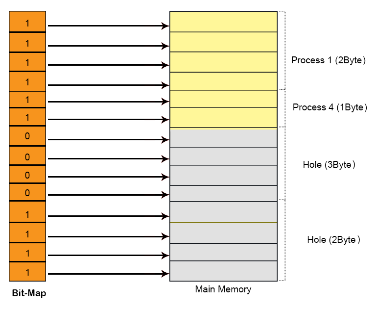
To keep track allocated and holes OS use Bit map data structure in main memory. Bit map contains either value 1 or 0. Total No of bits in bit map will always equal to Total No of Allocation units in main memory. In using diagram 14 allocation units are required to represent 7-Byte memory So, 14 bits are required for bit map. Each allocation unit is represented by 1-bit of bit-map data structure as shown in the following diagram. Corresponding bit for process is 1 and for hole is 0.

Assume a process 4 of size 1Byte wants to load in main memory then OS will scan the Bit map and search the contagious number of Zero’s. If space is available then that process will load successfully. So P4 will load successfully and its corresponding bits turns to 1 as shown in below diagram.
At this point suppose Process 3 is complete then its corresponding bits in bit-Map turn to 0 as explain in the following diagram.
Conclusion:
When a process complete it execution period, then its memory becomes free available which is a de-allocation method. And all its corresponding bits in bit-Map turns to Zero.
when a process load in main memory then its corresponding bits in bit-Map turns to 1 which is a allocation method.
Disadvantages of Using Bitmap
1. The OS has to assign some memory for bitmap to store the details about allocation and de-allocation.
Smaller the size of allocation unit more will be the memory required for Bit-Map. Explained Under
if Size of 1 allocation unit = 4 bits (1/2 Byte) then
Size of bitmap = total main memory/ (size of allocation unit in bit + bit required for bit-map)
                      = 1/(4+1)= 1/5 of total main memory.
If Size of 1 allocation unit = 8 bits (1 Byte)
Size of bitmap = total main memory/ (size of allocation unit in bit + bit required for bit-map)
= 1/ (8+1) = 1/9 of total main memory. If we increase the size of allocation unit then size of bit-map will reduced but some space may waste as given below in diagram. Because, two processes cannot exist in one allocation unit at a time, but one process can exist in more than one contiguous allocation units.
2. To find any hole in the memory, the OS has to search for 0s in the bitmap. This searching takes a lot of time which makes the system inefficient.
This searching happens through link-list. we will see the link-list in the next post.
Linked List In Dynamic Partitioning
Linked list is used to find free or filled partitions in dynamic partitioning. In link list there are different nodes and partitions are available where one node represents one partition and other node represents the other node. OS maintains the the Link List.
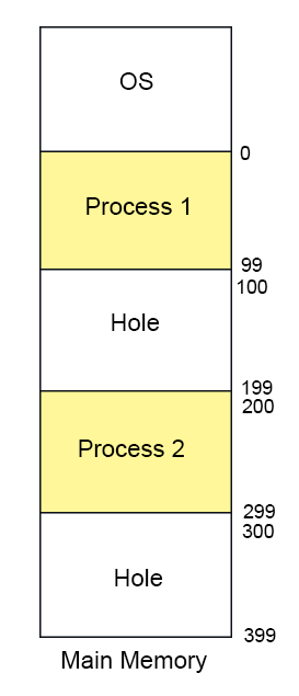
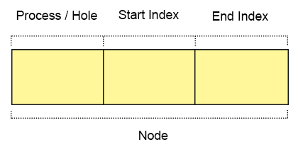
Every node has three fields
- First field: First field of the node holds a flag bit (0, 1) which shows whether the partition is a free/hole or some process is inside.
- Second field: Second field of node stores the starting index of the partition.
- Third filed: Third field of node stores the end index of the partition.
Types of Linked list In Dynamic Partitioning
1. Single Link List
Single link list, traverse only in forward direction. It can detect only holes or process but cannot merge the adjacent holes.
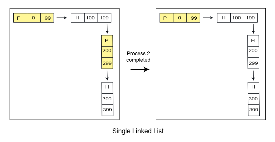
2. Double Link List
Double link list, traverse in both forward and backward directions. It can detect holes and can merge the adjacent partitions of holes as well.
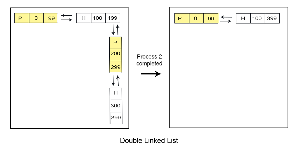
Advantages of double linked list over single link list
Reduce the No. of partitions will increase the degree of multi-programming.
Paging In OS with Examples
Paging is a technique of Non-Contiguous where one process can reside at different locations of main memory. So, spanning is totally possible. In this post we will see all bout paging with examples.
Need of Paging
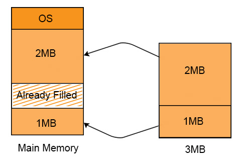
The main disadvantage in Contiguous Dynamic Partitioning was External fragmentation. Although, External fragmentation may remove by Compaction but it makes the system inefficient.
In paging, external fragmentation was totally remove without compaction.
Explain with Example
P1 requires 3 MB space to load in the main memory. We have two holes of 2MB and 1MB respectively available at different locations in main memory. And still Process 1 can load successfully. It is because of non-contiguous memory allocation.
Concept of Paging
In which processes are organized in equal size blocks called pages and the main memory is organized in equal sized blocks called frames.
Pages at secondary memory and frames at main memory both have the same size. As, CPU does not generate absolute address. But it generates the logical address.
But the actual data required to CPU present in main memory. Physical address is requiring to access actual data in main memory. For this purpose, system use the MMU. MMU further use the Page table. Every process has its own page table.
Entries of page table of each process = total no of pages of that process
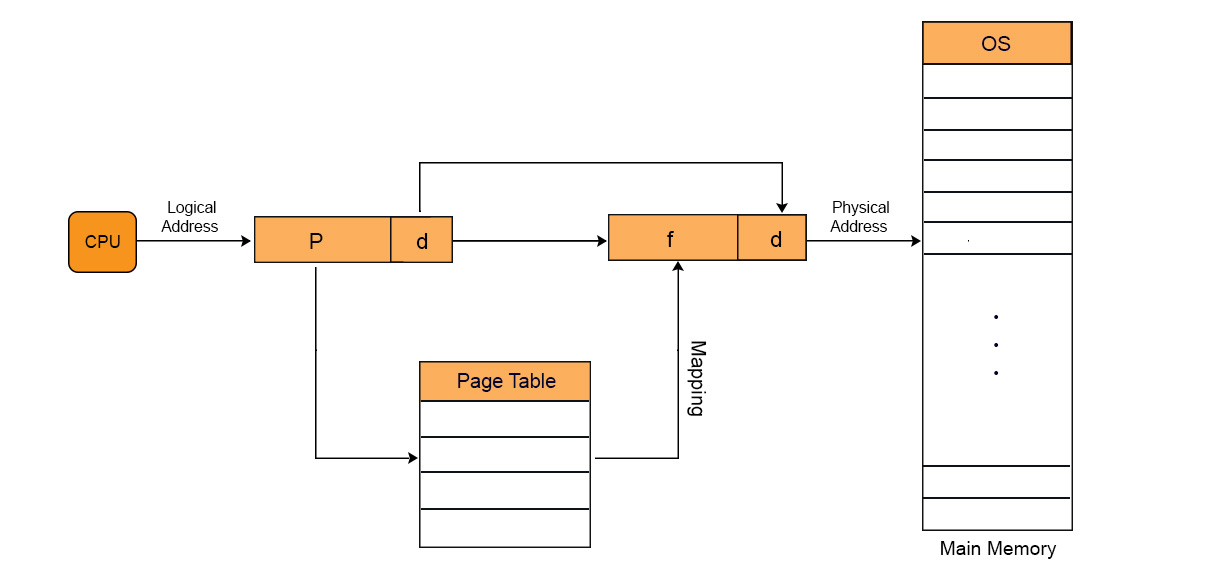
Paging is a technique in which the main memory is organized in equal sized blocks. These blocks also known as pages. In this technique, the address of occupied pages of physical memory is stored in a table, which is known as page table.
Through Paging, OS can get the physical memory location without specifying the lengthy memory address in the instruction. In this technique, the virtual address is use to map the physical address of the data. The length of virtual address is specified in the instruction and is smaller than physical address of the data. It consists of two different numbers, first number is the address of page which is known as virtual page in the page table. Second number is the offset value of the actual data in the page. Let explain with diagram
Lets Explain with example.
Multilevel Paging in OS
Entry of each page of a process is recorded into its page table. If page table size is greater than its frame then OS further divide the page table into equal frame size. So, that page table could easily be accommodate into the frame. it is all multilevel paging in OS.
Page Table Base Register value is stored in Outer most table of that process. We move outer most to inner most table to find the required address.
Important.
In the same way, if the size of second level page table is greater than frame size then we again divided 2 level page table into equal frame size and third level page table is generated and so on.
Multilevel paging with example
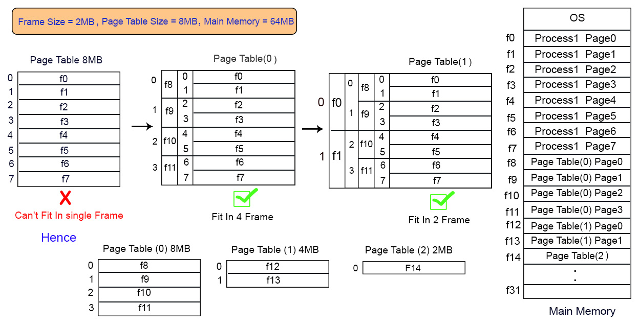
If there is a process of 8 pages and its page table size is 8MB while the frame size of main memory is 2MB. Then page table cannot fit into single frame so we have to load this table into multiple frames.
As size of Page table is 8MB so divide it into 4 equal page tables of 2MB each. These 4 page tables are loaded into different frames as shown in diagram.
Inverted Page Table
Need of Inverted Page table
Most of the Operating Systems use a separate page table for each process as in normal paging. In normal paging if there are 100 process then 100 will be the page tables in main memory. Sometimes when a process size is very large then its page table size also increases considerably. Through inverted page table, the overhead of storing an individual page table for each process is removed. A global page table is used which is utilized by all processes.
Example: If A process size is 2 GB with Page size = 512 Bytes and page table entry size is 4 Bytes, then
- Number of pages in the process = 2 GB / 512 B = 222
- Page Table Size = 222 * 22 = 224 bytes
If multiple processes running simultaneously in an OS with large sizes, then a considerable amount of memory is occupied by page tables only.
Various efforts are made to utilize the memory efficiently and to maintain a good balance in the level of multi-programming and efficient CPU utilization.
Working
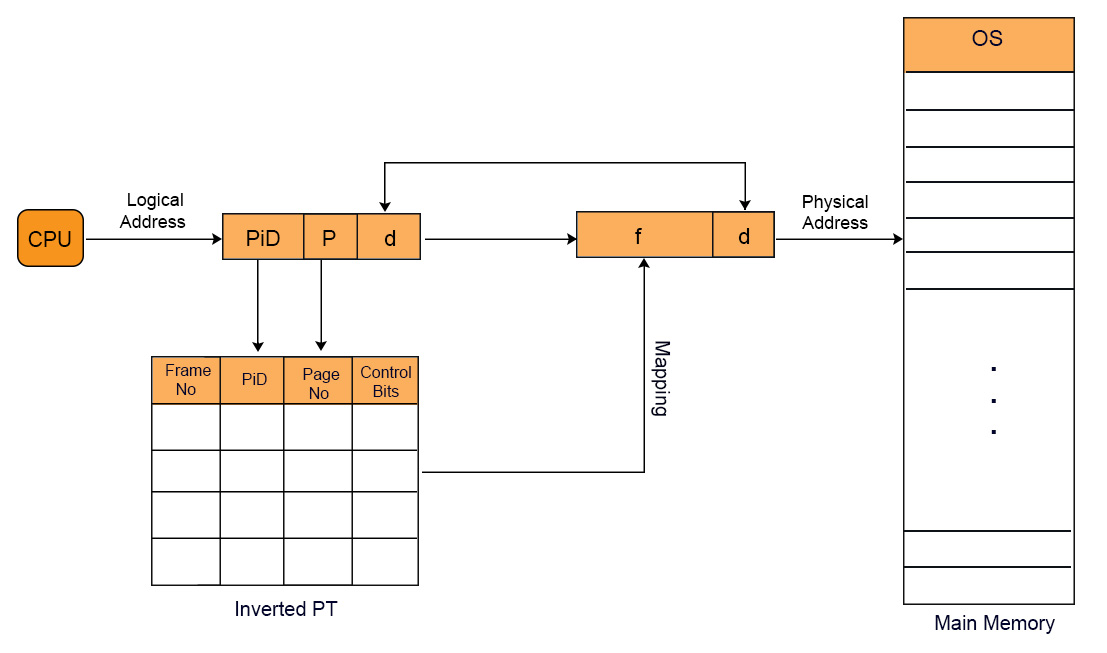
In inverted page table indexing is done with frame numbers instead of the logical page number. Each entry in the page table contains the following fields.
- Frame No: It specifies the Frame where the page no is actually present in main memory
- Page number:It specifies the page number which is required.
- Process id: An inverted page table contains pages of all the processes in execution. So page No may be same of different process but Process Id of each process is unique. Through Process ID we get the desired page of that process.
- Control bits –These bits are used to store paging table entry information. These include the valid/invalid bit, protection, dirty bit, reference bits, and other information bit.
- Chained pointer:It is possible when two or more processes share some part of main memory. In simple words, when two or more logical pages need to map to same Page Table Entry then a chaining pointer is used.
No of frames in main memory = No of entries in Inverted page table
Example
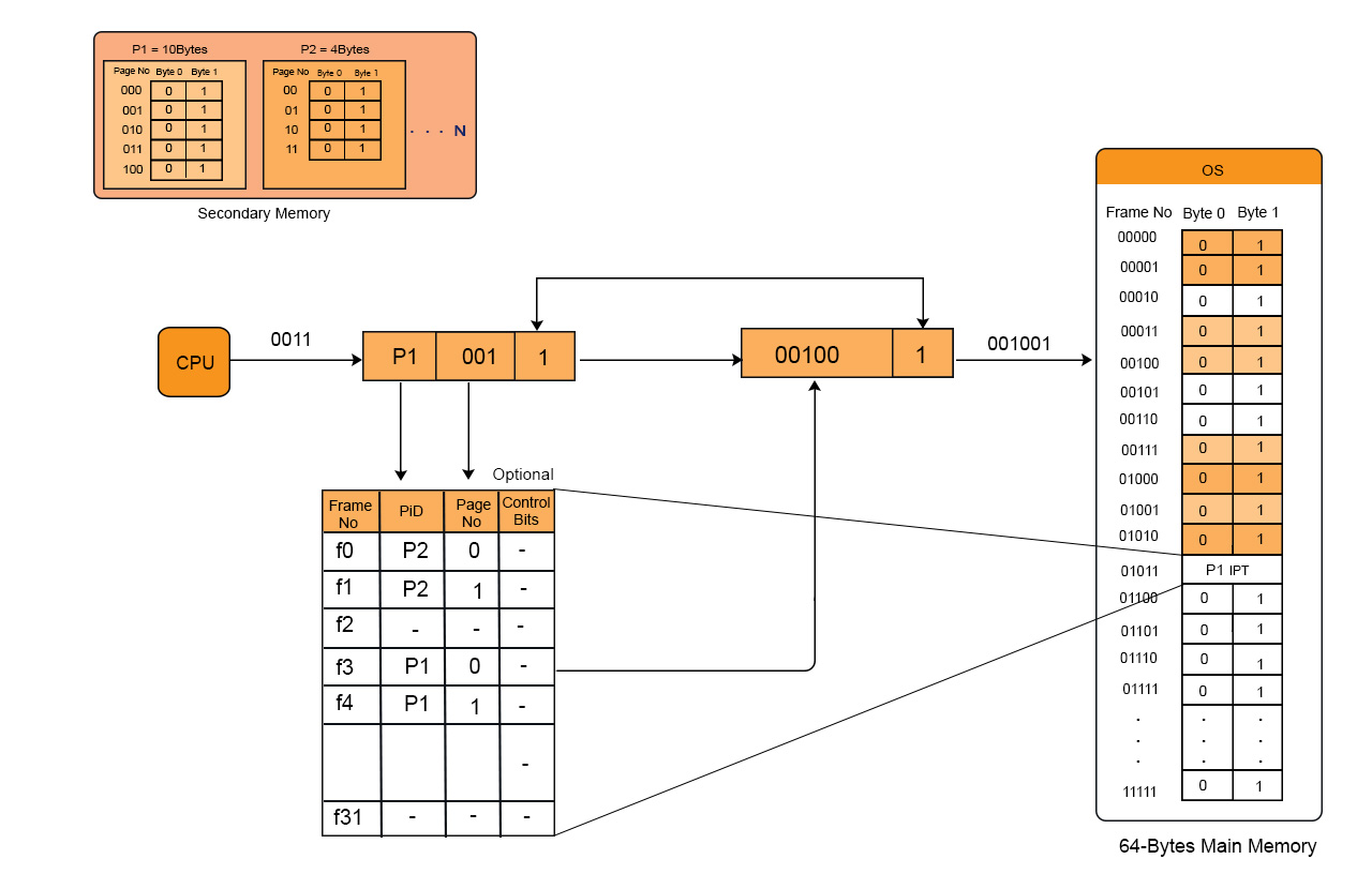
We have to linear search as we want to find page 2 of process 3 then
The logical address generated by the CPU contains Process ID, Page No, and Page Offset.
Through searching in Inverted Page Table, Process ID and Page No of logical address are compared with Process ID and Page No.
If match found then its corresponding frame number is obtained from page table entry otherwise page fault is occur and Demand paging comes into picture.
Note: No. of Entries in Inverted page table = No. of frames in Physical address Space
Advantages and Disadvantages:
- Reduced memory space
- Longer Search time
Translation Look aside Buffer (TLB)
You must have the concept of paging before to learn Translation lookaside Buffer. But In term of paging, we have to access the main memory twice or more for accessing a page.
- Once when we get the Page table from main memory.
- And second when we get the particular page from main memory of corresponding frame.
In this way, main memory is accessed twice in paging and even more than twice while using multilevel paging. So it was time consuming.
This problem is overcome by using TLB. TLB is hardware component and is a part of MMU. TLB works like Cache Memory. It Exists within CPU casing and in some cases it found on IC chip.
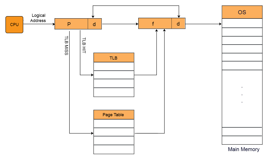
Working of TLB
when CPU generates virtual address of any page then it first look that particular page in TLB.In case of TLB hit, data is directly accessed from main memory without accessing the main memory twice or more.
In case of TLB miss, OS have to repeat the concept of paging again to find required page. After getting that particular page from main memory, it first loaded into TLB . So that, if CPU demand for this page in later, then it could be easily access from TLB, without repeating the paging.
TLB contains Tag (Process No + Process ID) and Frame. Page Number is compared with Tag .As, it contains pages of only running processes. So, Process ID is not compulsory. Lets look at TLB diagram given under,
TLB only contains the pages that are accessible to the current process. If process A is currently running, then TLB will contains only the translation (Logical to physical address) for the pages of process A. If process B is currently running then there will be no page of Process A in TLB and vice versa.
When CPU switches from one process to another process then TLB of currently running process is also cleared. This process is also known as flushing of TLB.
Translation Look aside Buffer VS Cache Memory
Both TLB and Cache memory are hardware’s exist within the CPU chip. The basic purpose of both these components is to access faster data. The major differences between TLB and Cache are.
| TLB | Cache Memory |
| 1. TLB is required only when Virtual Memory is used by CPU. | 1. Cache memory is the basic component of modern system. |
| 2. TLB is used to speed up address translation for Virtual memory so that page table is not need to access for every address. | 2. CPU Cache is used to speed up main memory access. Most recently and most frequently data is present in Cache memory. If data is found in Cache the there is no need to go for RAM. |
| 3. TLB performs operations at the time of address translation by MMU. | 3. CPU cache performs operations at the time of memory access by CPU. |
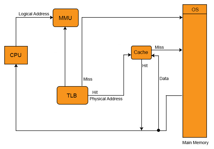
Cache and TLB working Model
In fact, in all modern CPU’s having the all Cache levels and TLB as well. Working Model of Cache and TLB with diagram,
Multiple TLBs
Same like the caches, TLBs also have multiple levels. Now a days CPU has multiple TLB’s. CPU may have three (ITLB1, DTLB1, TLB2) or four TLBs. These TLB’s s are differing in Speed and capacity from it’s others types.
Question on TLB
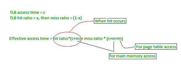
Effective Memory Access Time Calculation Formula’s
TLB_hit_time: = TLB_search_time + memory_access_time
TLB_miss_time: = TLB_search_time + memory_access_time + memory_access_time
EMAT: = hit_ratio * TLB_hit_time + (1- hit-ratio) * (TLB_miss_time)
OR
EMAT: = hit_ratio * (TLB_search_time + memory_access_time) + (1 – hit_ratio) * (TLB_search_time + 2*memory_access-time)
If hit ratio is denoted By “P”, TLB search time is “t” and TLB memory access time is “m” then EMAT will be.
EMAT = P(t+m) + (1-P)(t+2m)
Question: A paging scheme using TLB. TLB access time 10ns and main memory access time takes 50ns. What is effective memory access time (in ns) if TLB hit ratio is 90% and there is no page fault.
Solution
EMAT: = hit_ratio * (TLB_search_time + memory_access_time) + (1 – hit_ratio) * (TLB_search_time + 2*memory_access-time)
= 90%(10+50) +10%(10+2(50))
=65ns
Segmentation in OS
Dividing the physical memory space into multiple blocks of same or different sizes is called Segmentation in OS. Each block has some length which is it’s segment. Starting address of the segment is the base address and The length of the segment tells the memory size of that segment.
Segment table contains mainly two values about segment:
- Base Value: It tells about the base address of the segment
- Limit Value: It tells about the size of the segment.
Need of Segmentation
Paging is more favorable to OS rather than the User. As in the concept of paging a process is divided into equal sized pages. It may divide the same function into different pages and those pages may or may not be loaded at the same time into the main memory. Let explain with example
Suppose, there is an Add () function which is divided in two different pages and these two pages are loaded in frame 3 and 4.Let suppose as CPU execute F3 and page fault occur and F4 replaced with any other frame then ADD() function is not executed completely . In this way efficiency of system is reduced.
So, this problem is overcome through segmentation. In segmentation, Each segment contains same type of functions such as main(), ADD() functions.
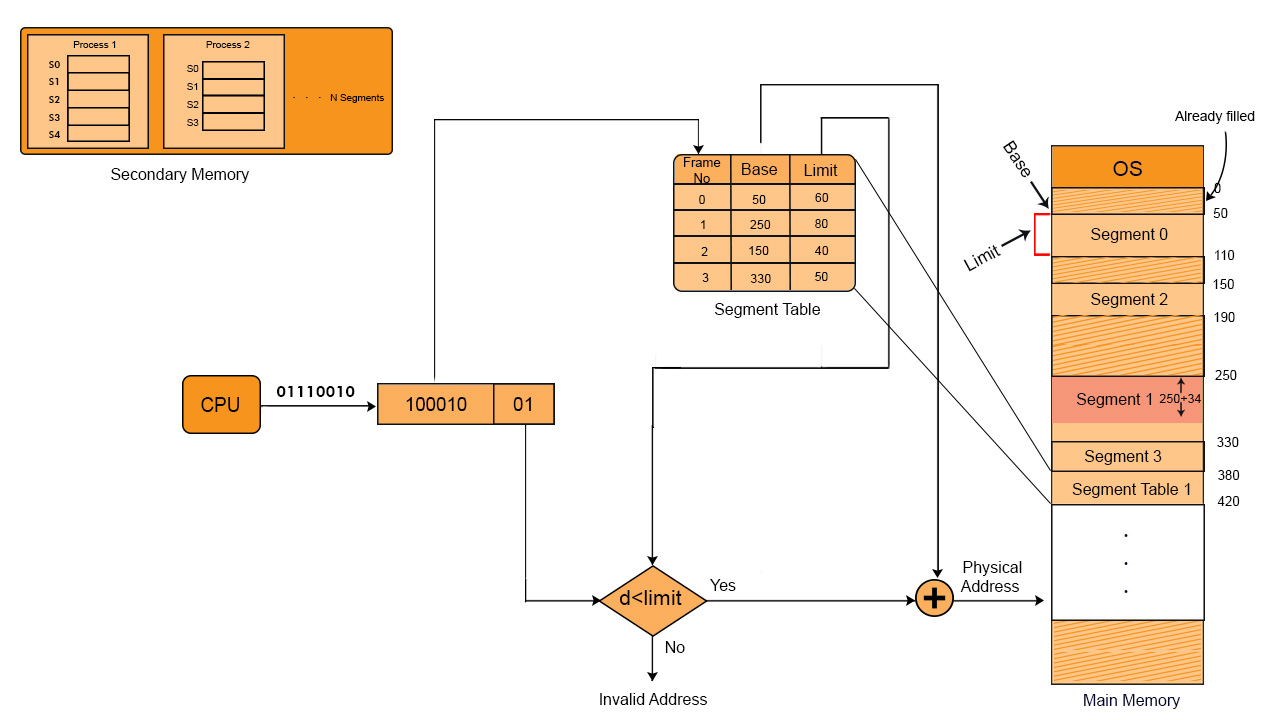
Logical address to physical address Translation
CPU generates the logical address which contains two parts.
i. Segment Number: When there is a need to obtain data from required segmented memory then the actual address of data is calculated by adding the base address of the segment with offset value.
ii. Offset:
The distance between the base address and actual position of data in segment is known as displacement or offset value.
The Segment number from logical address is mapped to the segment table in main memory. The offset of the respective segment is compared with Limit. If the offset is less than limit then it is a valid address otherwise it return an invalid address.
If the address is valid then Physical address can be calculated by the addition of base address and offset of respective segment from ?main memory.
In diagram given below, we will use the short forms as, S is Segment No, d is offset and f is Frame No.
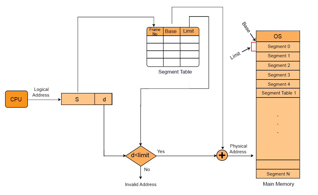
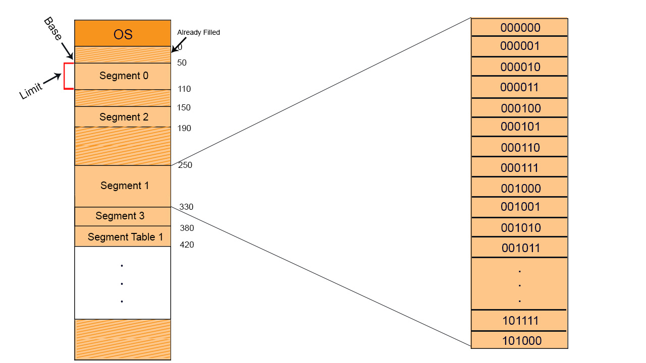
We can fetch whole segment or some part of the segment. If CPU wants to fetch segment 1 then it look at segment table where base address is 250. If its displacement size (d) is 50 then from 250 to 300 memory locations are fetched. And if displacement value is 80 then 250 to 330 values are fetched explanation is given in the diagram below,
Let suppose we have two process P1 and P2 at secondary memory with 5 and 4 segments respectively
Values of each segment will be like that as show in the below diagram
Advantages of Segmentation
- Segment table size is less than page table size.
- No internal fragmentation
- Average Size of Segment is larger than the actual size of page.
Disadvantages
- It can have external fragmentation.
- Costly memory management algorithms.
Paged Segmentation and Segmented Paging
A big challenge with single level paging is that if the logical address space is large, then the page table may take up a lot of space in main memory. For instance, consider that logical address is 32 bit and each page is 4 KB, the number of pages will be 2^20 pages. The page table without additional bits will be of the size 20 bits * 220 or 2.5 MB. Since each process has its own page table, a lot of memory will be consumed when single level paging is used. For a system with 64-bit logical address even a page table of single process will not fit in main memory. For a process with a large logical address space, a lot of its page table entries are invalid as a lot of the logical address space goes unused.

Page table with invalid entries

Segments of a process
The size of the page table can be reduced by creating a page table for each segment. To accomplish this hardware support is required. The address provided by CPU will now be partitioned into segment no., page no. and offset.

The memory management unit (MMU) will use the segment table which will contain the address of page table(base) and limit. The page table will point to the page frames of the segments in main memory.

Segmented Paging
Advantages of Segmented Paging
- The page table size is reduced as pages are present only for data of segments, hence reducing the memory requirements.
- Gives a programmers view along with the advantages of paging.
- Reduces external fragmentation in comparison with segmentation.
- Since the entire segment need not be swapped out, the swapping out into virtual memory becomes easier .
Disadvantages of Segmented Paging
- Internal fragmentation still exists in pages.
- Extra hardware is required
- Translation becomes more sequential increasing the memory access time.
- External fragmentation occurs because of varying sizes of page tables and varying sizes of segment tables in today’s systems.
Paged Segmentation
- In segmented paging, not every process has the same number of segments and the segment tables can be large in size which will cause external fragmentation due to the varying segment table sizes. To solve this problem, we use paged segmentation which requires the segment table to be paged. The logical address generated by the CPU will now consist of page no #1, segment no, page no #2 and offset.
- The page table even with segmented paging can have a lot of invalid pages. Instead of using multi level paging along with segmented paging, the problem of larger page table can be solved by directly applying multi level paging instead of segmented paging.

Paged Segmentation
Advantages of Paged Segmentation
- No external fragmentation
- Reduced memory requirements as no. of pages limited to segment size.
- Page table size is smaller just like segmented paging,
- Similar to segmented paging, the entire segment need not be swapped out.
Disadvantages of Paged Segmentation
- Internal fragmentation remains a problem.
- Hardware is complexer than segmented paging.
- Extra level of paging at first stage adds to the delay in memory access.
Cache Organization & Locality of Reference
Cache Memory is a special very high-speed memory. It is used to speed up and synchronizing with high-speed CPU. Cache memory is costlier than main memory or disk memory but economical than CPU registers. Cache memory is an extremely fast memory type that acts as a buffer between RAM and the CPU. It holds frequently requested data and instructions so that they are immediately available to the CPU when needed.
Cache memory is used to reduce the average time to access data from the Main memory. The cache is a smaller and faster memory which stores copies of the data from frequently used main memory locations. There are various different independent caches in a CPU, which store instructions and data.
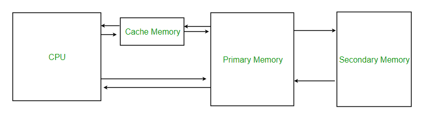
Levels of memory:
- Level 1 or Register –It is a type of memory in which data is stored and accepted that are immediately stored in CPU. Most commonly used register is accumulator, Program counter, address register etc.
- Level 2 or Cache memory –It is the fastest memory which has faster access time where data is temporarily stored for faster access.
- Level 3 or Main Memory –It is memory on which computer works currently. It is small in size and once power is off data no longer stays in this memory.
- Level 4 or Secondary Memory –It is external memory which is not as fast as main memory but data stays permanently in this memory.
- If the processor finds that the memory location is in the cache, a cache hit has occurred and data is read from cache
- If the processor does not find the memory location in the cache, a cache miss has occurred. For a cache miss, the cache allocates a new entry and copies in data from main memory, then the request is fulfilled from the contents of the cache.
The performance of cache memory is frequently measured in terms of a quantity called Hit ratio.
Hit ratio = hit / (hit + miss) = no. of hits/total accessesWe can improve Cache performance using higher cache block size, higher associativity, reduce miss rate, reduce miss penalty, and reduce the time to hit in the cache.
Locality of reference refers to a phenomenon in which a computer program tends to access same set of memory locations for a particular time period. In other words, Locality of Reference refers to the tendency of the computer program to access instructions whose addresses are near one another. The property of locality of reference is mainly shown by loops and subroutine calls in a program.
- In case of loops in program control processing unit repeatedly refers to the set of instructions that constitute the loop.
- In case of subroutine calls, everytime the set of instructions are fetched from memory.
- References to data items also get localized that means same data item is referenced again and again.
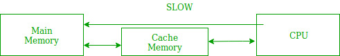
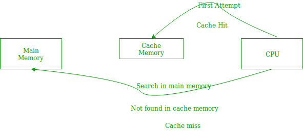
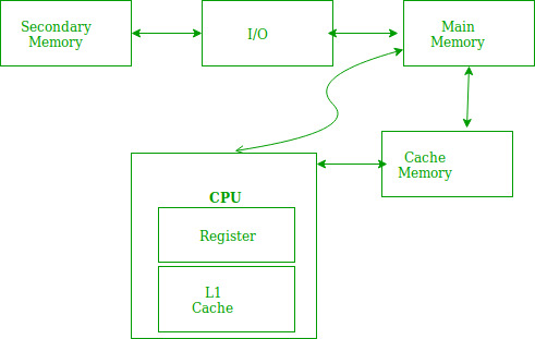
In the above figure, you can see that the CPU wants to read or fetch the data or instruction. First, it will access the cache memory as it is near to it and provides very fast access. If the required data or instruction is found, it will be fetched. This situation is known as a cache hit. But if the required data or instruction is not found in the cache memory then this situation is known as a cache miss. Now the main memory will be searched for the required data or instruction that was being searched and if found will go through one of the two ways:
- First way is that the CPU should fetch the required data or instruction and use it and that’s it but what, when the same data or instruction is required again.CPU again has to access the same main memory location for it and we already know that main memory is the slowest to access.
- The second way is to store the data or instruction in the cache memory so that if it is needed soon again in the near future it could be fetched in a much faster way.
- Temporal Locality –Temporal locality means current data or instruction that is being fetched may be needed soon. So we should store that data or instruction in the cache memory so that we can avoid again searching in main memory for the same data.

When CPU accesses the current main memory location for reading required data or instruction, it also gets stored in the cache memory which is based on the fact that same data or instruction may be needed in near future. This is known as temporal locality. If some data is referenced, then there is a high probability that it will be referenced again in the near future.
- Spatial Locality –Spatial locality means instruction or data near to the current memory location that is being fetched, may be needed soon in the near future. This is slightly different from the temporal locality. Here we are talking about nearly located memory locations while in temporal locality we were talking about the actual memory location that was being fetched.

Hit + Miss = Total CPU ReferenceHit Ratio(h) = Hit / (Hit+Miss)
Average access time of any memory system consists of two levels: Cache and Main Memory. If Tc is time to access cache memory and Tm is the time to access main memory then we can write:
Tavg = Average time to access memoryTavg = h * Tc + (1-h)*(Tm + Tc)
Page Table and Mapping
Page table is a data structure used by a virtual memory in a computer OS to store the mapping in-between virtual addresses and physical addresses.
It maps the page number to its frame number where that particular page is stored. CPU generates the logical address of page but main memory recognizes the Physical address. Then Page Table maps the logical address to Physical address.
Main characteristics of page Table
- When a process is loaded to execute then its page table is also loaded in main memory. Page table contains the information about every entry of page which is loaded into the frame of main memory.
- Size of page table varies from process to process. Having the more entries into page table greater the size will be and vice versa.
- Page size of process is always equal to frame size of main memory. If the page size is 2Bytes the size of frame is also 2Bytes because pages are loaded into frames of main memory.
- Each process has its unique independent table
Greater the number of entries in page table of a process then higher will be the size of page table. IF the size of page table is greater than frame size of main memory then Multi-level paging comes into picture. look at diagram of page table given below for more details.
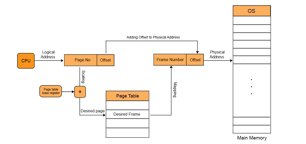
Logical to Physical Address mapping through Page Table
There are four main steps for mapping the logical to physical address through page table.
1. Generation of logical address
CPU creates logical address for each page of process. This created address holds two things:
- page number: it tells the required page of process
- offset: it tells the specific byte from that page
2. Scaling
CPU use the page table base register to store the base address of page table. The value of page table base register is added to the page number. So that, the actual location of that page in the page table, can be obtained.
3. Generation of physical Address
When the required page is found in the page table then its corresponding value which is frame number is easily obtained. It is the physical address because it is the address of main memory where the actual data is present.
Physical address also has two parts
- Frame number: it is the address of main memory where the CPU request page is present.
- Offset: offset of the logical address is similar to offset of physical address. So, it will copy from the logical address to physical address.
4. Getting Actual Frame Number
Frame number and offset of the physical address are mapped to the main memory. So that, the actual byte or word address could be accessed.
Let explain Page Table and Mapping with example
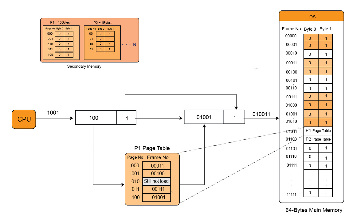
Let process P1 and P2 having the size 10Bytes and 8Bytes respectively, exist in secondary memory. There are 5 pages of process 1 and 4 pages of process 2 but each page has size of 2bytes. Let suppose, 4 pages of process 1 and 4 pages of process 2 are exist in the main memory. But the page table contains the whole record of its pages whether they are loaded in main memory or not. Let suppose CPU request for the 2nd byte of 5th page of process 1 which exist in main memory. Then the explanation with diagram is.

Step 1: Generation of Logical address:
1001 is the Logical address where page No is 100 and 1 is offset.
Step 2: Scaling
Base address registers value 000. Because page table base register value is 000.
By adding of page no and page table base register the result is 100. Then 100 is CPU required page .
Step 3: generation of Physical address
Corresponding frame of page 100 is 01001.
Copy the offset of logical address and add it to frame no. Then the result is 010011. So, 010011 is the required frame number in main memory.
Step 4: Getting actual page no.
So, 010011 is the actual physical address where the data of required page is present. Now CPU can get the required data easily.
In the very next lectures we will see the page table entries.
Page Table Entries
Page table has page table entries and each page table entry contains a frame number and optional status like present/Absent bit, Protection, Reference, Caching and Dirty bit.
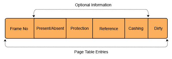
1. Frame Number:
It gives the frame number of main memory for required page.
2. Present/absent bit:
Present or absent bit tells about the presence or absence of particular page you are looking for in main memory. If required page is found then it is a case of Page Hit and denoted by 1. But If required page is not found then it is a case of Page Fault and denoted by 0. Page fault is control by OS, using virtual memory concept.
3. Protection bit:
Protection bit tells about the protection that you want to apply on that page. There are three permissions are available on any pages which are read, write and executes
4. Referenced Bit
Referenced bit tells whether this page has been accessed in the last clock cycle or not. If it accessed earlier then reference bit set to 1. If this page referred first time then reference bit set to 0.It is used in memory access algorithms like LRU etc.
5. Caching Enabled/Disabled
Cache is a memory which is faster and closer to CPU. Least Recently used information’s are stored in Cache. Cache can be enabled or disabled for pages.
Sometimes we need the fresh data (Dynamic). As If we use an account and our balance is dynamically change with the time then in such cases, keep cache disabled.
Sometimes we need the Static data as a video which we use again and again then for this type of tasks cache can be enabled.
6. Modified bit:
It is also called dirty bit. it tells whether the page has been modified or not. If the value of modified bit is 1 then it means the value of this page is updated in RAM by CPU with the permission of Process Write. And If dirty value=1, then OS will update the value of this page in hard disk. If dirty value=0, then it means no changing is performed in RAM by CPU.


No comments:
Post a Comment